![]() 1-800-Simpson
1-800-Simpson

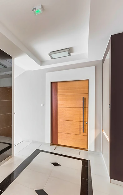
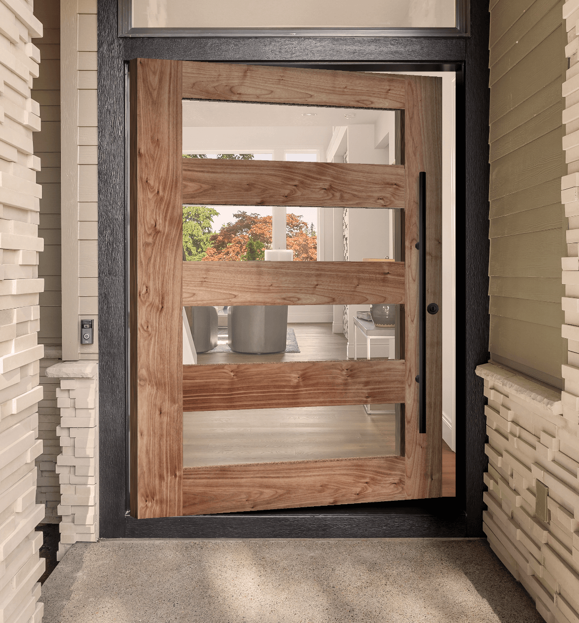

Simpson Pivot Door System Installation Guide
One of the benefits of the Simpson Pivot Door System is its ability to be installed in an existing door rough opening, as well as new construction. And since these systems are relatively new to the industry, there is not as much field installation experience as with typical side-hinged doors. To help your installation go as smooth as possible, we have created the following step-by-step guide. Please read this guide completely before installing your Simpson Pivot Door System.
Finish Considerations:
For best performance, Simpson recommends you install the door slab into the door frame once. Therefore, consider finishing the door and frame either before installation or in place, immediately after the door has been installed. For complete care & finishing recommendations, visit simpsondoor.com/care-finishing
Hardware Considerations:
Do not remove the pivot hardware or multipoint lock—if supplied with unit—at any time. These have been installed at the factory so only minor on-site calibrations will be needed.
(Figure 1)

(Figure 2)
Installation Instructions:
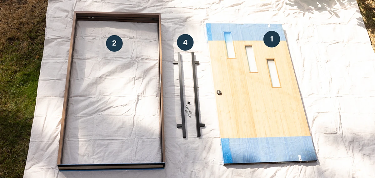
Step 1: Inspect Your Pivot System and Read All Installation Instructions
The crate for your system has been specifically designed to fit typical trucking requirements plus ensure your unit arrives free of shipping damage. It is important to review your system’s components before installation. And if you feel any component has been damaged, please notify your Simpson Authorized Dealer immediately upon inspection. Note: sharing photos is very helpful during this process. Your system includes:
- Door component with...
- Pivot system hardware (FritsJurgens® brand) installed within both the top and bottom of the door
- Multi-point locking and latch hardware (Fuhr brand) installed in the latch side of the door
- If an exterior door, brush sweep system installed into the bottom and top of the door
- Assembled Frame with...
- If an exterior door:
- The pivot door plate is installed into the ADA aluminum (or low-profile wood) sill
- Pivot door plate installed into header jamb
- Hardware to accept the multi-point lock and latch on the latch side jamb leg
- Protective metal plate to accommodate the roller latch, on the latch side jamb leg
- Weatherstrip on each of the jamb legs
- If an interior door:
- The pivot door plate is supplied with hardware for installation
- Pivot door plate installed into header jamb
- Protective metal plate to accommodate the roller latch, on the latch side jamb leg
- If an exterior door:
- Materials for door installation and adjustment
- Large axel wrench for rotating pivot spindle on bottom of door
- Long hex key for top pivot installation
- Small wrench and install guide for fine-tuning the door’s movement
- Small hex key for door latch adjustment
- Wood plugs for your optional use to cover screws used to install the frame
- Plywood door installation template for the bottom of door
- Plywood door installation template for the top of door
- Appliance straps
- If provided with system, 2 handle pulls plus hardware (Hoppe® brand) for handle pull installation
Step 2: Prepare the Door Unit and Install the Frame
- Parts of your door system include protective wrap or cardboard. When possible, leave this protection in place until door installation is complete. If protective wrap/cardboard needs to be removed to help with installation, make sure to handle unprotected pieces with care and lay out unprotected pieces on protected surfaces only.
- Prepare the site as you would a standard door unit.
- Your frame has been supplied with a plywood skid plate—if an exterior unit it is attached to the sill, if an interior unit it is attached to the jamb legs—that is to be removed before frame installation.
- The bottom of the sill is flat and must be placed on a completely flat and level surface in order for the door to operate correctly.
- Two screws hold the top pivot plate in place within the header
jamb. These screws intentionally stick out above the header
jamb. Make sure to back out those screws slightly so they
do not extend beyond the header when installing the frame.
These screws can be driven back in after the frame is installed
(See Figure 3).
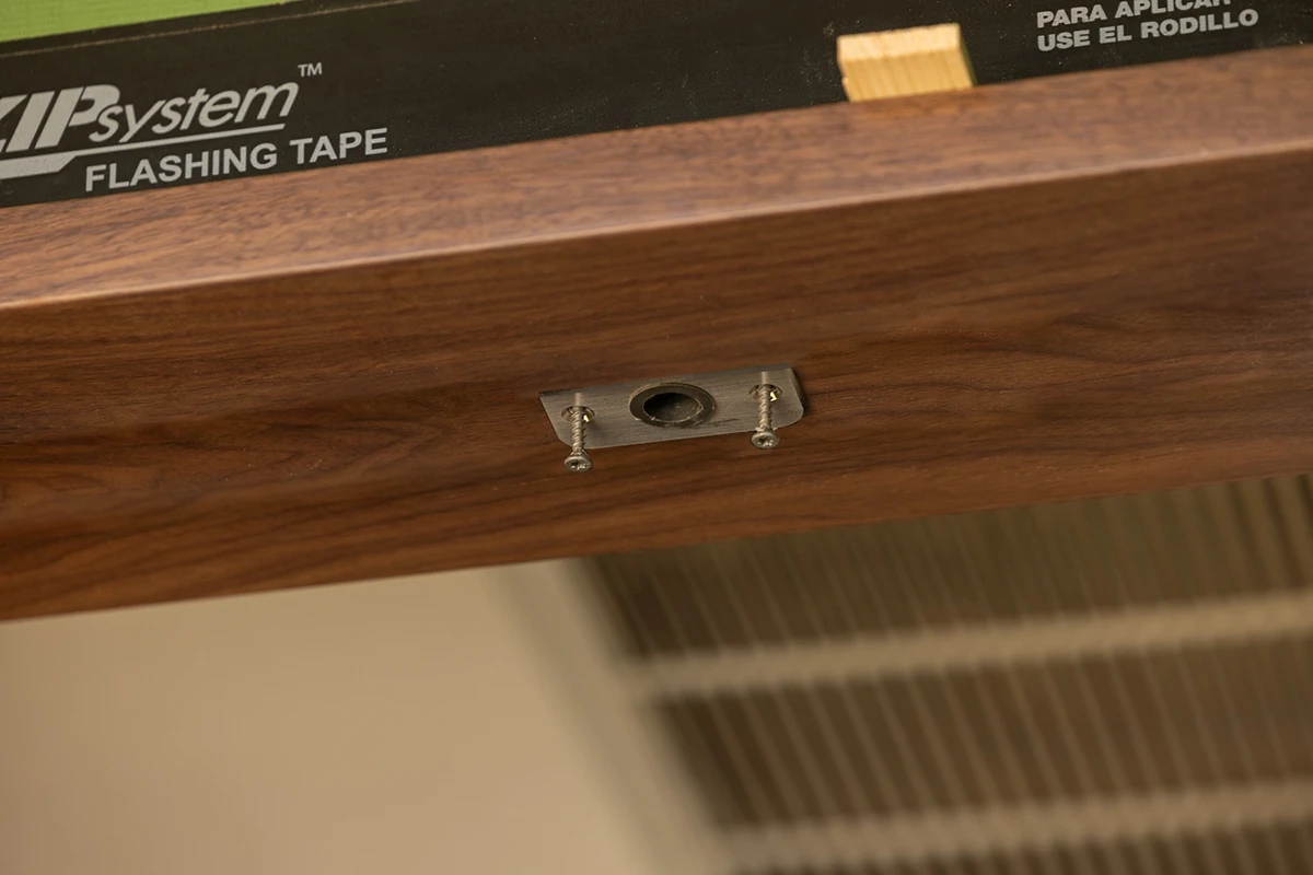
(Figure 3) - Install the frame—without the door—like you would a standard door unit. Ensure all components sit level and even within the rough opening, using shims as needed. Frame must be plumb and square to ensure proper operation. Sill must be flat and level.
- If installing an exterior door:
- Secure the sill to the floor with waterproof construction adhesive.
- Secure the jamb legs and header with long decking screws (not included). Use at least 4 screws through each jamb leg and at least 3 screws through the jamb header.
- If installing an interior door:
- Install the pivot door floor plate with the included Fritzjeurgens installation instructions.
- Secure the jamb legs and header with long decking screws (not included). Use at least 4 screws through each jamb leg and at least 3 screws through the jamb header
Please note: It is best to place screws on jamb legs behind the weatherseal so screws are not visible. For screws into the header, they can be countersunk and then hidden with the supplied wood plugs or left uncovered.
Step 3: Install the Door Component into the Frame
- The size and weight of your door will determine the number of people needed for installation. A minimum of 3 people will be needed and larger doors may require 4.
- Simpson Pivot doors have been engineered as an inswing unit, which means most of the door swings into a home (exterior door) or room (interior door) and these instructions have been written for an inswing unit. If you have specified an outswing unit (uncommon) for your application, please understand that while following these instructions.
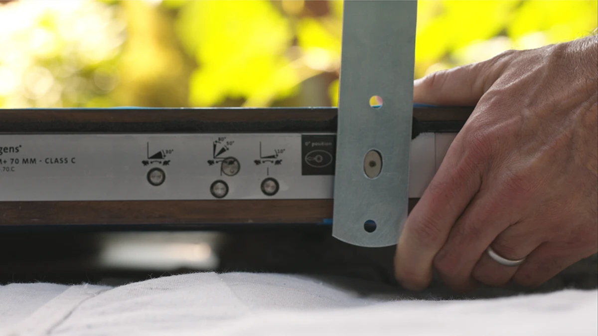
- Before picking up the door, we are going to ensure that the pivot hardware is prepared for the installation process.
- Bottom of door – the factory setting for the pivot spindle on
the bottom of the door is to have the arrow on the end of the
spindle point toward the brush sweep (exterior side of the
door). If this setting has adjusted in transit, use the included
large axle wrench to turn the spindle ¼ turn back to the
factory setting (See Figure 4). While you are looking at the
hardware from the perspective of the bottom of the door,
make note of the 3 adjustment screws labeled “Speed,”
“Damper” and “Latch.” You will be adjusting these screws
with the small wrench during Step 6.
(Figure 4) - Top of door – the pivot spindle should be fully retracted into the door. If it is sticking out of the door, retract it back fully into the door using the long hex key in the bottom of the two holes on the side of the door.
- Bottom of door – the factory setting for the pivot spindle on
the bottom of the door is to have the arrow on the end of the
spindle point toward the brush sweep (exterior side of the
door). If this setting has adjusted in transit, use the included
large axle wrench to turn the spindle ¼ turn back to the
factory setting (See Figure 4). While you are looking at the
hardware from the perspective of the bottom of the door,
make note of the 3 adjustment screws labeled “Speed,”
“Damper” and “Latch.” You will be adjusting these screws
with the small wrench during Step 6.
- Position the plywood door installation template – marked with
FOR BOTTOM OF DOOR – on the door sill against the jamb
leg – carefully pulling out the weatherstrip so the template can
rest flush against the jamb - on the pivot side of the door and
against the exterior side of the sill. (See Figure 5).
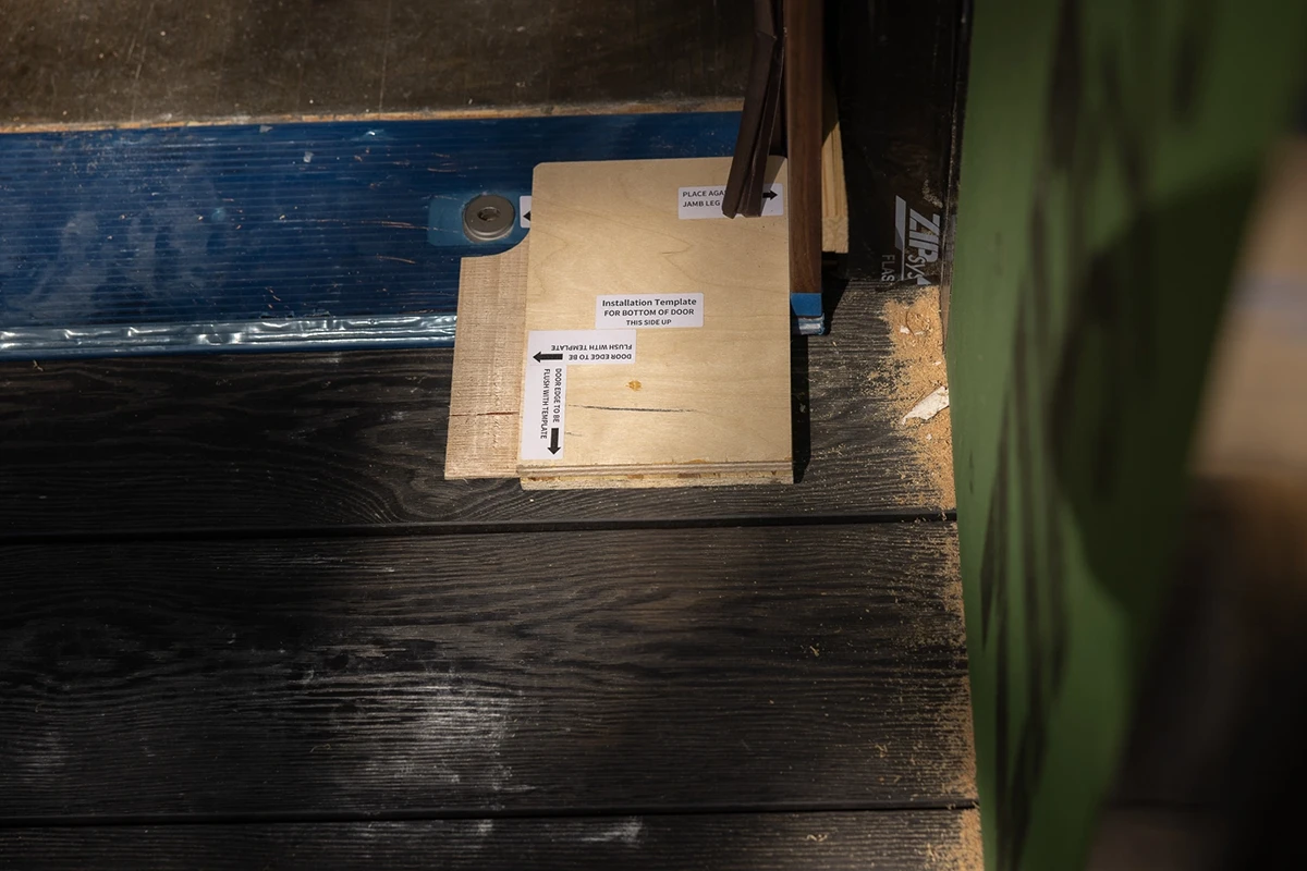
(Figure 5) - Prepare your door to go into the frame. You will be installing the door by bringing it through the frame from the outside of the opening, perpendicular to the frame. And since an inswing pivot door will have more door on the inside when open, you will lead the door into frame with the side that has the multi- point lock already installed.
- Position one person on each end of the door for lifting, plus one person on the side of the door toward the latch side of the frame. This will be your team to lift and tilt the door into place. Use more people and/or the appliance straps as your door requires.
- Tilt up your door so it is standing up outside of the frame and perpendicular to the frame.
- With a person on each end, lift and carry your door through the frame, with the multi-point lock as the leading edge. A slight tilt of the door toward the latch side of the frame will be necessary in order to get the full door height through the frame. A third person will be needed to help steady the door while tilted.
- Guide the bottom of the door into the door installation template, all while ensuring the template is pushed snug against the outside of the sill and the door jamb. This template will ensure the pivot spindle sticking out from the bottom of the door will fit directly into the floor plate. You can use the arrow stickers to help with alignment.
- Insert the pivot spindle into the floor plate. Once complete, set aside the BOTTOM OF DOOR installation template.
Step 4: Top Pivot Spindle Installation and Adjustment
- Once the spindle on the bottom of the door is in the floor plate, the person helping with the tilt of the door will now be installing the top pivot, while the other two hold the door in place.
- Position the plywood door installation template – marked with FOR TOP OF DOOR – on top of the door against the jamb leg—carefully pulling out the weatherstrip so the template can rest flush against the jamb—on the pivot side of the door and against the exterior side of the jamb head. This will align the top pivot spindle for easy installation.
- Please note: there are two holes on the side of the door
near the top (See Figure 6). The long hex key (provided) will
be used within these two holes for pivot installation and
adjustment. The hex key will be a straight shape for doors 4’0”
or wider, and it will be an L shape for doors under 4’0”.

(Figure 6) - Insert the hex key into the bottom of the two holes and turn clockwise, which will extend the top pivot spindle into the top pivot plate. Ensure the top pivot is securely installed and remove the plywood installation template. Tuck the weatherstrip at both the top and bottom of the door back into the kerf in the jamb.
- Gently swing the door to ensure the reveals—distance between the side of the door and frame—are the same on each side of the door. Small adjustments in the top pivot will likely be needed to ensure the reveals are the same. These adjustments are made using the long hex key into the top of the two holes on the side of the door. These adjustments can be made by turning the key in either direction.
- If provided with system, the pull handles should now be installed. See Hoppe handle installation instructions.
Step 5: Adjust Roller Latch on Latch Side of Door
- The roller latch in the Simpson pivot system allows the door to latch when pulled closed, and will need a final adjustment.
- Use the small hex key to make an adjustment to how far the latch extends into door frame.
- Test the latch by pulling the door open and closed multiple times. The door should latch when closed, and provide slight resistance when opening. Make adjustments as needed.
Step 6: Make Adjustments to Pivot Swing Speed and Operation
- Your pivot hinge operation can be personalized to your specifications. Use the small wrench and FritsJurgens 3-step installation card to make your adjustments. (See Figure 7)
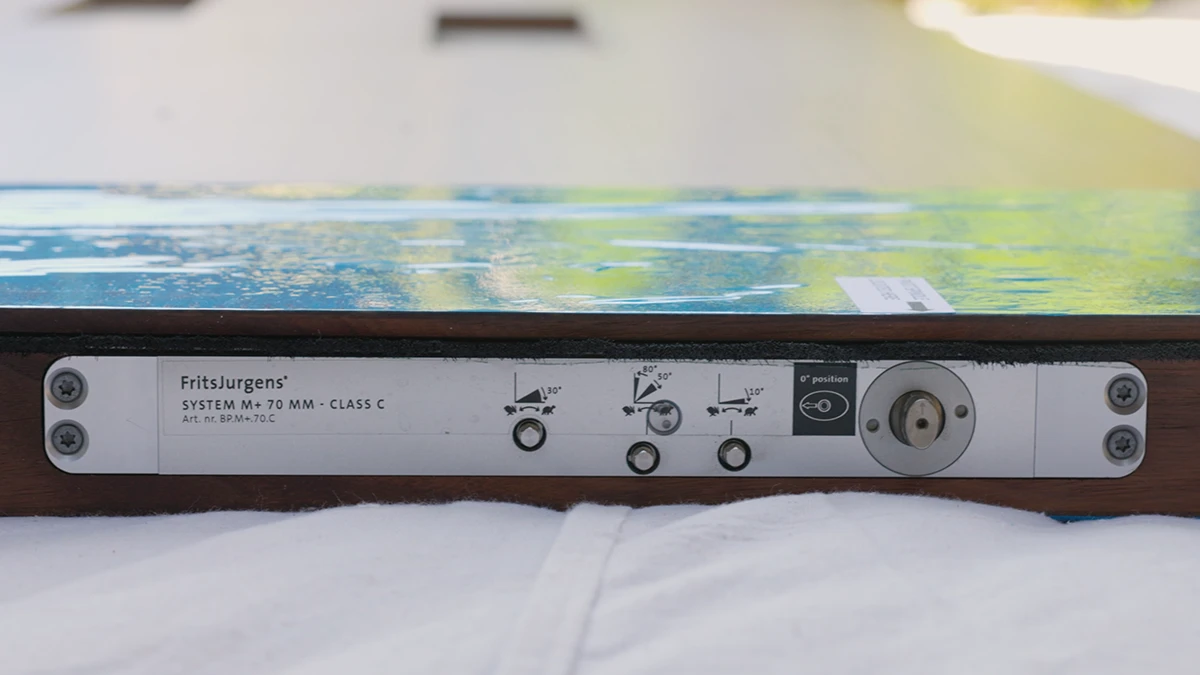
(Figure 7)- Step 1 – go to the inside of your pivot door and lay the card on the floor, either on side A or B based on the swing direction.
- Step 2 – adjust the damper – controlling how far the door will swing open.
- Step 3 – adjust the speed of the swing.
- Step 4 – adjust the operation of the door as it latches.
Final Step: Remove Packaging and Final Adjustments, as Needed
- If not removed already, packaging and protective wrap can be carefully removed from the door and sill. If using a knife to remove packaging, take care to not cut into the door, frame or sill.
- The installer is responsible for the installation process, which includes any final calibration to the frame, top pivot hinge, roller latch and pivot operation.

Explore Doors
Find a Door Design Tools Gallery Project Center Where To Buy
About Simpson
Our History
Environment
Press Room
Privacy Policy
FAQs
Contact Us
Careers
California Supply
Chains Act
Professionals
EZQ Authorized Dealer Program Builders/Contractors Architects Company Store

INSPIRATION
at your door®
![]()
![]()
![]()
![]()
![]()
![]()
#SimpsonDoor
Copyright © 2026 Simpson Door Company. All rights reserved.